Vend Motor / Spiral Jam Resolution
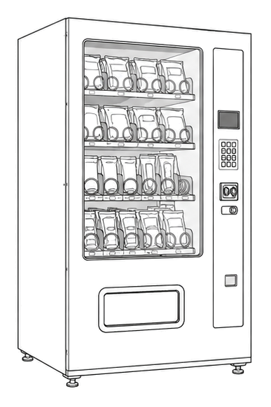
Automatic Products Ap 937 Satellite
Vend Motor / Spiral Jam Resolution
Diagnose and resolve issues where a product selection fails to vend due to mechanical binding or motor electrical failure.
Qualified technician handoff: stop before live electrical testing, sealed-system refrigeration work, compressor service, or protected-compartment access unless a qualified technician is handling the work.
- Voltage exceeds expected tolerance or reads 0V when active: Halt measurement, do not jumper connections.
- Burning smell, visible arcing, or damaged insulation: Remove power immediately.
- Main controller fails to output logic signal: Ensure replacement guards passed before ordering board.
Checklist
Guided Diagnostic Steps
Work from low-risk checks toward technician-level inspection only when evidence supports it.
You can read or print the route now. The first checkbox click opens the service contact gate.
- 1
Inspect Tray and Spiral Alignment
operator-intermediatelowWith machine power on but door open, initiate a vend for the failed selection. Observe the spiral movement.
Flashlight or Shop LightStop conditions- Burning smell detected
Expected: Identify whether the motor turns, spirals bind, or coupling slips.
Evidence to note: photo
- 2
Clear Mechanical Jam and Verify
operator-intermediatelowCarefully remove the jammed product. Manually rotate the spiral to ensure it turns freely without grinding. Verify correct spiral size for the product.
Expected: Spiral rotates smoothly 360 degrees with no product binding.
Evidence to note: note
- 3
Verify Tray Harness Connection
operator-intermediatehighTrace the wire harness from the motor back to the tray connector. Ensure the connector is fully seated and free of corrosion.
Flashlight or Shop LightStop conditions- Damaged wiring insulation
Expected: Secure physical connection established.
Evidence to note: photo
- 4
Measure Motor Drive Voltage
technician-advancedlive-voltageInitiate a vend while measuring DC voltage at the motor harness connector. Note: This requires backprobing or a breakout harness.
Qualified technician handoff: stop before live electrical testing, sealed-system refrigeration work, compressor service, or protected-compartment access unless a qualified technician is handling the work.
Digital MultimeterStop conditions- Any sign of short circuiting or arcing
Evidence to note: meter-reading
- 5
Check Controller Output
technician-advancedlive-voltageVerify if the main controller is sending the vend signal to the tray harness header.
Qualified technician handoff: stop before live electrical testing, sealed-system refrigeration work, compressor service, or protected-compartment access unless a qualified technician is handling the work.
Digital MultimeterExpected: Control signal matches expected logic level during vend.
Evidence to note: meter-reading
- 6
Stop and Hand Off
operator-intermediatelowHalt diagnostic process. Advanced electrical fault or safety hazard detected. Secure machine and escalate.
Expected: Machine safely disabled and tagged for senior technician.
Evidence to note: note
Tools for this route
Location Help
Where to find this
Use this as orientation before touching the machine. It is location help, not a repair instruction.
Start at the customer delivery bin and product drop path; clear visible product and debris before moving to internal checks.
- Holds inventory and translates motor rotation into linear product movement for vending.
- Product trays (3W, 4W, 5W configurations)
- 24VDC motors (180° and 360°)
- Auger couplings
Do not open protected compartments unless a qualified technician is handling the work.
cabinet glass front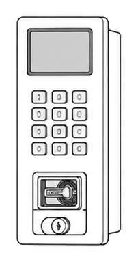 display keypad
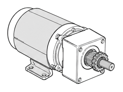 vend motor
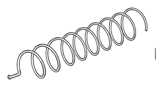 spiral coil
Parts status
Exact public parts list not verified yet. Use this route to identify the system before ordering.
Candidate areas for part verification
Other Possible Issues
Switch routes if this symptom is not the closest match.