No Power Diagnostic Flow
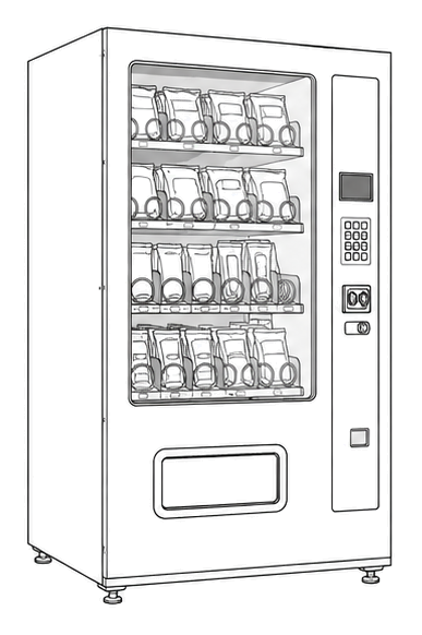
Automatic Products Countertop C Serie
No Power Diagnostic Flow
Verifies wall outlet power and internal power connections to the logic board.
Qualified technician handoff: stop before live electrical testing, sealed-system refrigeration work, compressor service, or protected-compartment access unless a qualified technician is handling the work.
- Wall outlet wiring reversed (polarity issue): Stop and hand off to licensed electrician.
Checklist
Guided Diagnostic Steps
Work from low-risk checks toward technician-level inspection only when evidence supports it.
You can read or print the route now. The first checkbox click opens the service contact gate.
- 1
Verify Wall Outlet Voltage
technician-advancedlive-voltageCheck the wall outlet for proper voltage and polarity.
Qualified technician handoff: stop before live electrical testing, sealed-system refrigeration work, compressor service, or protected-compartment access unless a qualified technician is handling the work.
Digital MultimeterStop conditions- Visible wiring damage to wall outlet.
Expected: Proper AC voltage detected with correct polarity.
Evidence to note: meter-reading
- 2
Check Internal Power Connections
operator-intermediatehighVerify the main power cord is securely connected to the interlock box and check for internal fuse integrity.
Digital MultimeterExpected: Connections are tight and fuse is intact.
Evidence to note: meter-reading
- 3
Inspect for Product Jam
operator-intermediatelowRemove the product from the suspected selection and check if the spiral turns freely by hand.
Expected: Spiral turns without resistance.
Evidence to note: note
- 4
Test Motor via Service Mode
operator-intermediatehighEnter the service test mode and command the specific motor to turn.
Expected: Motor cycles one full turn.
Evidence to note: photo
- 5
Check Motor Harness
operator-intermediatehighTrace the wiring from the motor back to the logic board for cuts or disconnections.
Expected: Wiring is intact and secure.
Evidence to note: photo
Tools for this route
Location Help
Where to find this
Use this as orientation before touching the machine. It is location help, not a repair instruction.

Start outside the machine at the outlet and cord, then identify the power entry area before any protected-compartment inspection.
- Supplies main 120V AC power and steps down voltage for logic and 24V components.
- Main power cord
- Transformer
- Main interlock box
Do not open energized or protected electrical areas unless a qualified technician or licensed electrician is handling the work.
cabinet countertop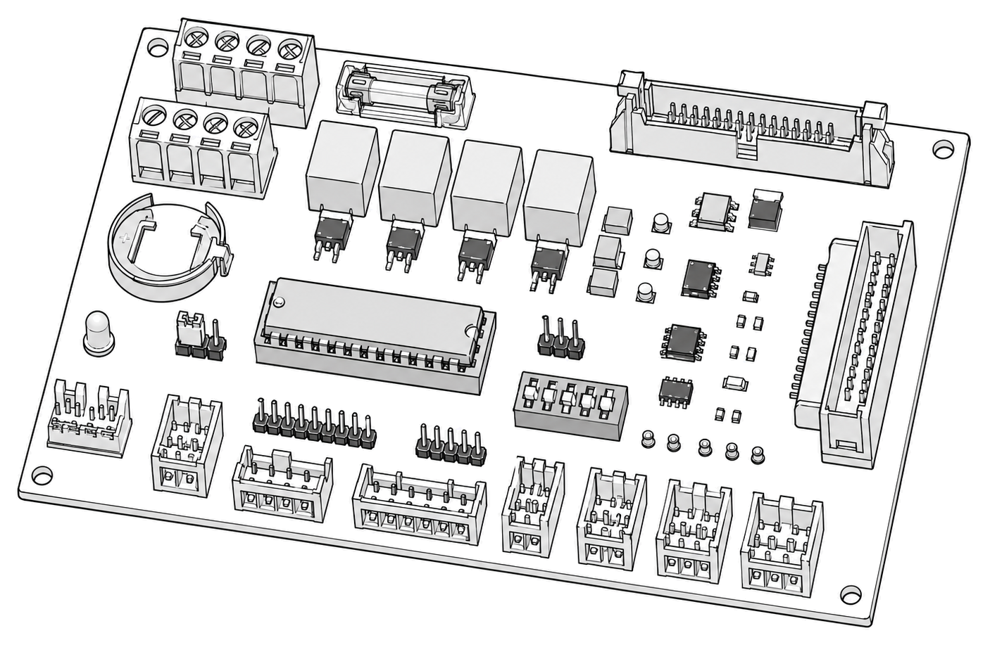 control board generic
 power supply
 terminal block
Parts status
Exact public parts list not verified yet. Use this route to identify the system before ordering.
Candidate areas for part verification
Other Possible Issues
Switch routes if this symptom is not the closest match.