Vend motor receives no drive signal
GPL GPL 106
Vend motor receives no drive signal
This diagnostic path investigates why a specific product dispensing motor fails to activate when the system is commanded to dispense, pointing toward potential signal loss or motor failure.
Qualified technician handoff: stop before live electrical testing, sealed-system refrigeration work, compressor service, or protected-compartment access unless a qualified technician is handling the work.
- Multiple motors on same tray fail simultaneously: Suspect common cause: tray PCB or harness. Do not replace individual motors until common cause is ruled out.
- Repeated motor failures on same position: Root-cause analysis needed. Possible mechanical binding or product loading issue.
- Because this involves high-risk electrical checks, a qualified technician must verify the signal path from the PCB to the motor.
- If motor resistance testing is required, a qualified technician must perform this procedure to prevent electrical hazards.
Checklist
Guided Diagnostic Steps
Work from low-risk checks toward technician-level inspection only when evidence supports it.
You can read or print the route now. The first checkbox click opens the service contact gate.
- 1
Ensure the machine is powered down and all relevant motor connections...
operator-intermediatehighEnsure the machine is powered down and all relevant motor connections are visually inspected for obvious damage.
Digital MultimeterFlashlight or Work LightStop conditions- Because this involves high-risk electrical checks, a qualified technician must verify the signal path from the PCB to the motor.
- If motor resistance testing is required, a qualified technician must perform this procedure to prevent electrical hazards.
Expected: Initial condition is documented before deeper diagnosis.
Evidence to note: note
- 2
Attempt to manually cycle the product selection mechanism to rule out...
operator-intermediatehighAttempt to manually cycle the product selection mechanism to rule out simple mechanical binding.
Digital MultimeterFlashlight or Work LightStop conditions- Because this involves high-risk electrical checks, a qualified technician must verify the signal path from the PCB to the motor.
- If motor resistance testing is required, a qualified technician must perform this procedure to prevent electrical hazards.
Expected: Initial condition is documented before deeper diagnosis.
Evidence to note: note
- 3
Disconnect the motor harness connector at the relevant tray PCB.
operator-intermediatehighDisconnect the motor harness connector at the relevant tray PCB.
Digital MultimeterFlashlight or Work LightStop conditions- Because this involves high-risk electrical checks, a qualified technician must verify the signal path from the PCB to the motor.
- If motor resistance testing is required, a qualified technician must perform this procedure to prevent electrical hazards.
Expected: Result is documented before continuing the route.
Evidence to note: note
- 4
Initiate a vend command while observing the motor shaft for any sign...
operator-intermediatehighInitiate a vend command while observing the motor shaft for any sign of movement or electrical activity.
Digital MultimeterFlashlight or Work LightStop conditions- Because this involves high-risk electrical checks, a qualified technician must verify the signal path from the PCB to the motor.
- If motor resistance testing is required, a qualified technician must perform this procedure to prevent electrical hazards.
Expected: Result is documented before continuing the route.
Evidence to note: note
- 5
Measure the voltage signal at the motor output pins on the PCB during...
operator-intermediatehighMeasure the voltage signal at the motor output pins on the PCB during a simulated vend command for a qualified technician.
Digital MultimeterFlashlight or Work LightStop conditions- Because this involves high-risk electrical checks, a qualified technician must verify the signal path from the PCB to the motor.
- If motor resistance testing is required, a qualified technician must perform this procedure to prevent electrical hazards.
Expected: Result is documented before continuing the route.
Evidence to note: note
Tools for this route
Location Help
Where to find this
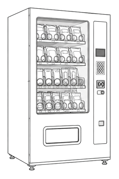
Use this as orientation before touching the machine. It is location help, not a repair instruction.
Start at the affected product shelf or selection row; compare the tray, coil, and product path with a nearby working selection.
- Drives spirals, belts, or pusher mechanisms to dispense product from tray positions.
- motor-and-pcb-assemblies
- ejector-shaft-gears
- wire-harness-clips
Do not open energized or protected electrical areas unless a qualified technician or licensed electrician is handling the work.
cabinet glass front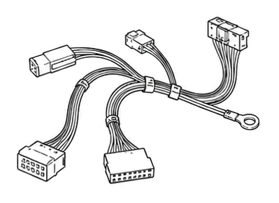 wiring harness
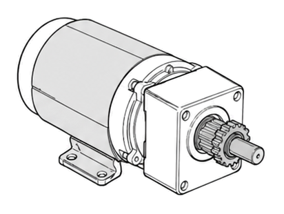 vend motor
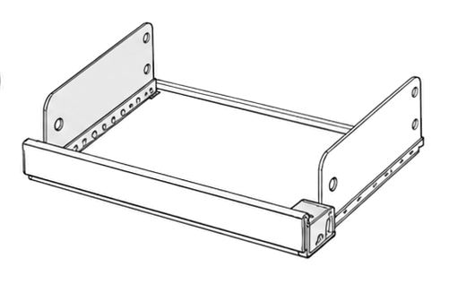 tray shelf
Parts status
Exact public parts list not verified yet. Use this route to identify the system before ordering.
Candidate areas for part verification
Other Possible Issues
Switch routes if this symptom is not the closest match.