Power Input and Control Board Check
GPL GPL Gpl116
Power Input and Control Board Check
Diagnoses total loss of power by verifying line voltage, internal fusing, and low-voltage transformer output.
Qualified technician handoff: stop before live electrical testing, sealed-system refrigeration work, compressor service, or protected-compartment access unless a qualified technician is handling the work.
- Line voltage measured at the transformer primary but zero voltage at secondary with no visible damage.: Escalate to manufacturer-or-licensed for potential sealed system or internal transformer fault evaluation.
Checklist
Guided Diagnostic Steps
Work from low-risk checks toward technician-level inspection only when evidence supports it.
You can read or print the route now. The first checkbox click opens the service contact gate.
- 1
Verify Line Voltage at Terminal Block
technician-advancedlive-voltageEnsure machine is unplugged, remove the lower back panel or access cover. Plug machine back in safely. Measure incoming AC voltage at the main terminal block.
Qualified technician handoff: stop before live electrical testing, sealed-system refrigeration work, compressor service, or protected-compartment access unless a qualified technician is handling the work.
Stop conditions- Burning smell detected
- Wetness inside electrical box
Expected: AC Voltage reads within expected range (e.g., 110-120V AC).
Evidence to note: meter-reading
- 2
Check Transformer Secondary Output
technician-advancedlive-voltageLocate the low-voltage transformer and safely measure the secondary output voltage.
Qualified technician handoff: stop before live electrical testing, sealed-system refrigeration work, compressor service, or protected-compartment access unless a qualified technician is handling the work.
Stop conditions- Transformer is hot to the touch
Evidence to note: meter-reading
- 3
Measure Voltage at Motor Connector
operator-intermediatehighPlace meter leads on the motor power pins at the harness connector. Initiate a vend cycle for the corresponding selection from the keypad.
Expected: Voltage spikes/reads during the vend command window.
Evidence to note: meter-reading
- 4
Check Harness Continuity
operator-intermediatelowUnplug machine. Disconnect harness from controller and motor. Check continuity of the motor drive wires.
Expected: Wires show near 0 ohms resistance.
Evidence to note: meter-reading
Tools for this route
Location Help
Where to find this
Use this as orientation before touching the machine. It is location help, not a repair instruction.

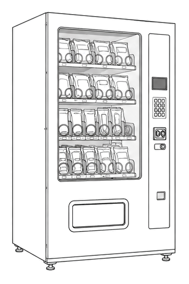
Start outside the machine at the outlet and cord, then identify the power entry area before any protected-compartment inspection.
- Supplies main AC voltage to the machine and steps it down for the control system.
- power cord
- line filter
- fuse or breaker
Do not open energized or protected electrical areas unless a qualified technician or licensed electrician is handling the work.
cabinet drink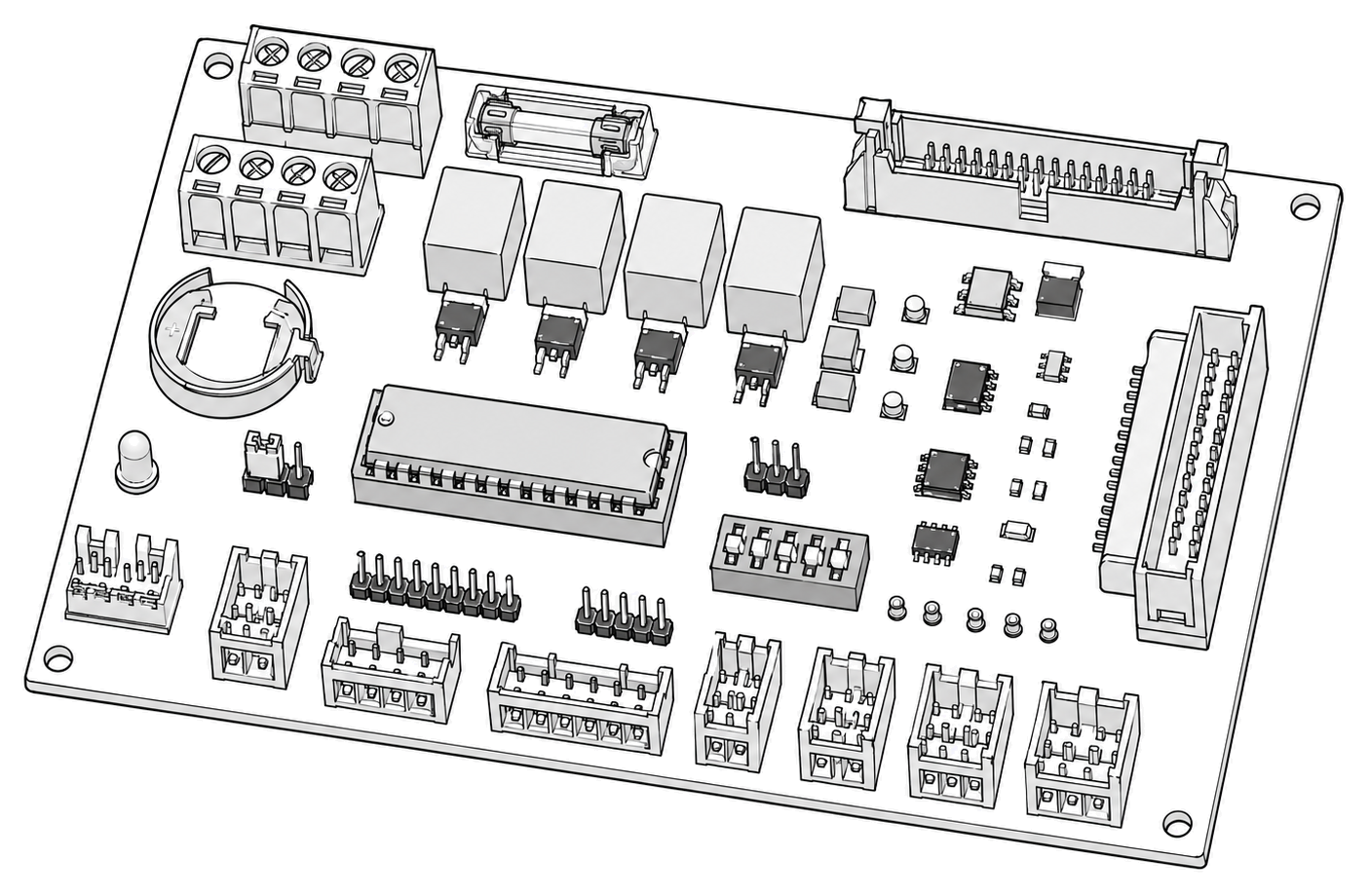 control board generic
 power supply
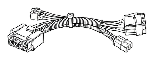 terminal block
Parts status
Exact public parts list not verified yet. Use this route to identify the system before ordering.
Candidate areas for part verification
Other Possible Issues
Switch routes if this symptom is not the closest match.