No Power Diagnostic Flow
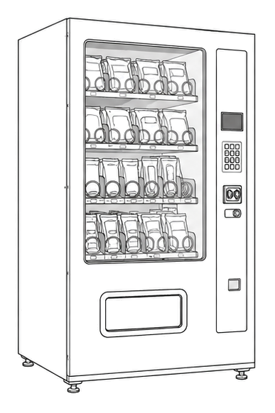
Automatic Products 211e 211e
No Power Diagnostic Flow
Verifies the electrical path from the wall outlet down to the main controller board.
Qualified technician handoff: stop before live electrical testing, sealed-system refrigeration work, compressor service, or protected-compartment access unless a qualified technician is handling the work.
- Voltage found on neutral/ground
- Zero resistance across line and neutral at cord
Checklist
Guided Diagnostic Steps
Work from low-risk checks toward technician-level inspection only when evidence supports it.
You can read or print the route now. The first checkbox click opens the service contact gate.
- 1
Verify Wall Outlet Voltage
technician-advancedlive-voltageEnsure the venue outlet is providing the correct voltage using a known-good tool or by plugging in a different device.
Qualified technician handoff: stop before live electrical testing, sealed-system refrigeration work, compressor service, or protected-compartment access unless a qualified technician is handling the work.
Digital MultimeterStop conditions- Signs of melted outlet
Expected: Outlet provides stable voltage matching machine requirements (115V or 220V).
Evidence to note: meter-reading
- 2
Inspect Power Cord
operator-intermediatelowVisually and physically inspect the length of the power cord for cuts, kinks, or burn marks.
Flashlight or Work LightStop conditions- Exposed copper wiring
- Smell of burning plastic
Expected: Cord is fully intact with no exposed wiring.
Evidence to note: photo
- 3
Check Main Power Switch
operator-intermediatelowLocate the main power switch on the power panel assembly and toggle it firmly to ensure it is fully engaged.
Expected: Switch physically clicks into position without feeling loose.
Evidence to note: note
- 4
Inspect Circuit Breakers
operator-intermediatehighCheck the position of all circuit breakers on the power panel. Reset any that appear tripped by firmly pushing them to the OFF position and then back to ON.
Flashlight or Work LightStop conditions- Breaker immediately trips again upon reset
Expected: All breakers physically reset to the ON position and machine powers up.
Evidence to note: photo
- 5
Verify Transformer Output Voltage
technician-advancedlive-voltageMeasure the AC voltage at the secondary (output) side of the main power transformer. Compare with the expected low voltage (e.g., 24VAC or 12VAC) specified in the machine's wiring diagram.
Qualified technician handoff: stop before live electrical testing, sealed-system refrigeration work, compressor service, or protected-compartment access unless a qualified technician is handling the work.
Digital MultimeterStop conditions- Transformer is physically hot or smells burnt
Expected: Transformer provides stable output voltage within specified tolerance.
Evidence to note: meter-reading
- 6
Check Controller Board Power Input
technician-advancedlive-voltageWith the machine powered on, carefully measure the DC voltage at the main power input pins of the controller board. This typically requires referencing the board's silk screen or wiring diagram for specific test points.
Qualified technician handoff: stop before live electrical testing, sealed-system refrigeration work, compressor service, or protected-compartment access unless a qualified technician is handling the work.
Digital MultimeterStop conditions- Signs of arcing or burnt components on the controller board
Expected: Controller board receives stable DC voltage (e.g., 5VDC or 12VDC) as specified.
Evidence to note: meter-reading
- 7
Inspect Display Harness Connection
operator-intermediatelowWith the machine powered OFF and unplugged, inspect the ribbon cable or harness connecting the controller board to the display panel. Ensure it is fully seated and free of damage.
Stop conditions- Visible burn marks on the harness or connectors.
Expected: Display harness is securely connected and undamaged.
Evidence to note: photo
- 8
Test with Known-Good Display Panel
operator-intermediatehighIf the display remains dark or corrupted after verifying controller power and harness, connect a known-good display panel (if available) to rule out a faulty display unit.
Stop conditions- No spare parts available.
Expected: Machine display functions correctly with the replacement display panel.
Evidence to note: photo
- 9
Terminal: Replace Power Transformer
technician-advancedlive-voltageIf no proper output voltage is detected from the transformer, and input voltage is confirmed, replace the power transformer.
Qualified technician handoff: stop before live electrical testing, sealed-system refrigeration work, compressor service, or protected-compartment access unless a qualified technician is handling the work.
Digital MultimeterScrewdriver SetExpected: New transformer restores correct power distribution.
Evidence to note: meter-reading
- 10
Terminal: Replace Main Harness or Power Supply
technician-advancedlive-voltageIf the controller board is not receiving correct power after verifying the transformer output, inspect and potentially replace the main wiring harness or any intermediate power supply modules between the transformer and the controller.
Qualified technician handoff: stop before live electrical testing, sealed-system refrigeration work, compressor service, or protected-compartment access unless a qualified technician is handling the work.
Digital MultimeterScrewdriver SetExpected: Controller board receives specified power, machine powers on.
Evidence to note: note
- 11
Terminal: Replace Controller Board
technician-advancedlive-voltageIf the controller board receives correct power but shows no signs of life (e.g., no status LEDs, no display output), it is likely faulty and requires replacement.
Qualified technician handoff: stop before live electrical testing, sealed-system refrigeration work, compressor service, or protected-compartment access unless a qualified technician is handling the work.
Screwdriver SetExpected: New controller board restores machine functionality.
Evidence to note: note
- 12
Terminal: Replace Display Harness
operator-intermediatehighIf the display harness is visibly damaged, replace it. Ensure proper routing to avoid future damage.
Screwdriver SetExpected: New harness restores display connection.
Evidence to note: note
Tools for this route
Location Help
Where to find this
Use this as orientation before touching the machine. It is location help, not a repair instruction.

Start outside the machine at the outlet and cord, then identify the power entry area before any protected-compartment inspection.
- Provides the primary electrical connection from the wall outlet to the machine's internal power panel.
- Power cord
- Terminal strip
- EMI filter
Do not open energized or protected electrical areas unless a qualified technician or licensed electrician is handling the work.
cabinet drink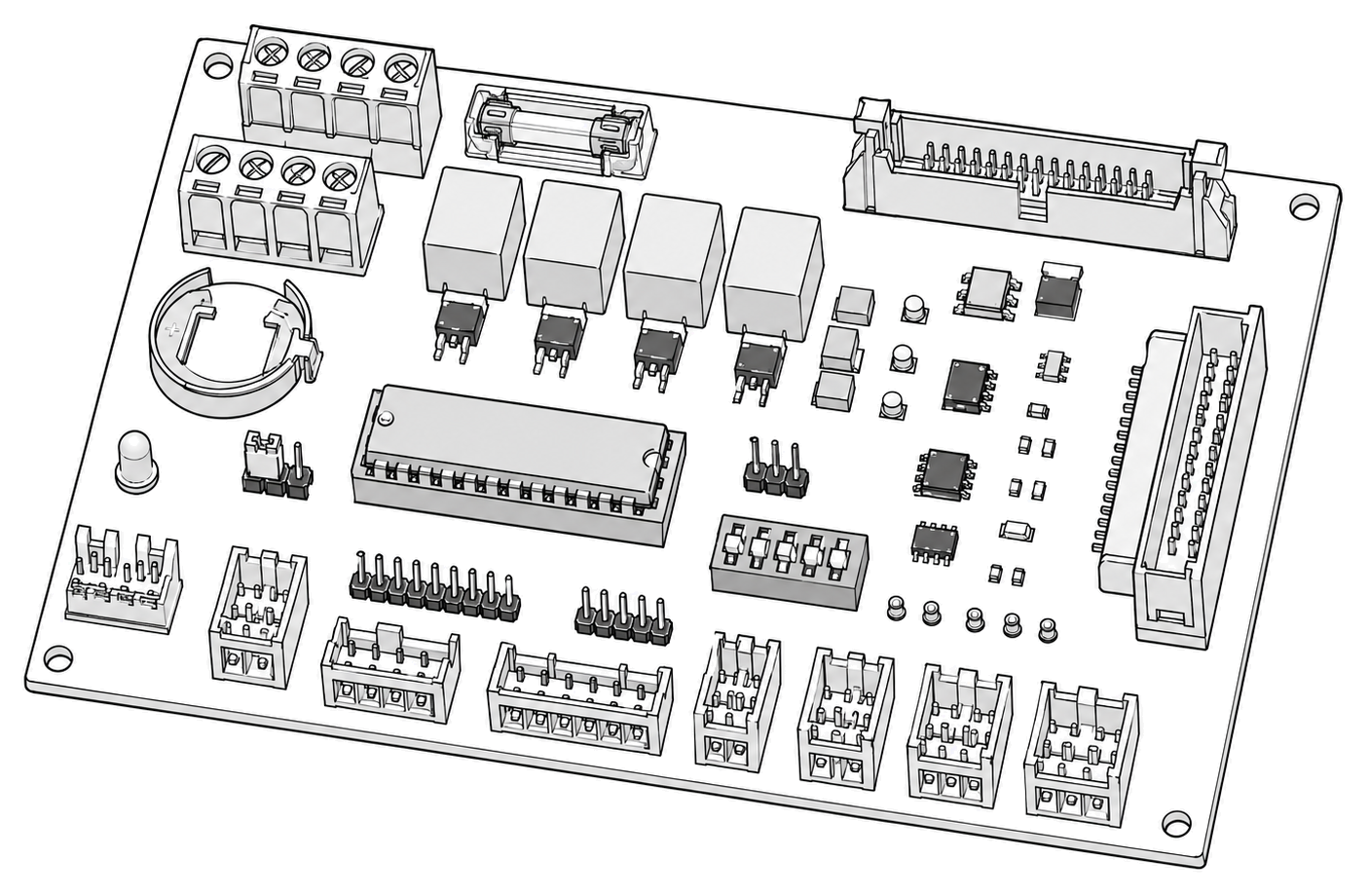 control board generic
 power supply
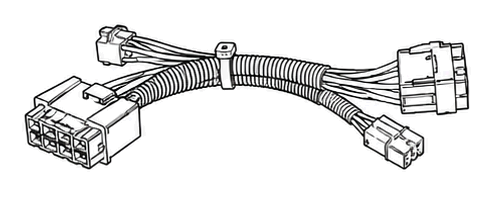 terminal block
Parts status
Exact public parts list not verified yet. Use this route to identify the system before ordering.
Candidate areas for part verification
Other Possible Issues
Switch routes if this symptom is not the closest match.