No Power Diagnostic Flow
GPL Snackcombo II
No Power Diagnostic Flow
Systematic check from wall outlet through power cord, internal fuse, and controller to isolate power loss.
Qualified technician handoff: stop before live electrical testing, sealed-system refrigeration work, compressor service, or protected-compartment access unless a qualified technician is handling the work.
- fuse-blows-again-after-replacement: stop-do-not-apply-power-escalate-to-licensed-technician
- burning-smell-at-any-point: unplug-immediately-do-not-proceed
Checklist
Guided Diagnostic Steps
Work from low-risk checks toward technician-level inspection only when evidence supports it.
You can read or print the route now. The first checkbox click opens the service contact gate.
- 1
Check Wall Outlet
operator-intermediatelowPlug a known-good lamp or outlet tester into the wall outlet serving the machine. Confirm the outlet has power.
Outlet TesterStop conditions- spark-or-arc-from-outlet-stop-and-call-facility-electrician
Expected: Lamp illuminates or tester shows correct wiring.
Evidence to note: note
- 2
Inspect Power Cord
operator-intermediatelowVisually inspect the full length of the power cord for cuts, kinks, discoloration, or exposed conductors. Confirm it seats firmly in the machine inlet.
FlashlightStop conditions- cord-feels-hot-stop-and-unplug
- visible-exposed-wire-stop-and-unplug
Expected: Cord is undamaged and firmly seated.
Evidence to note: photo
- 3
Check Internal Fuse
operator-intermediatehighWith machine unplugged, locate the main fuse holder. Remove and test fuse for continuity using a multimeter.
Digital MultimeterStop conditions- fuse-blown-and-scorch-marks-visible-stop-and-escalate
- burning-smell-stop-and-do-not-reapply-power
Expected: Fuse shows continuity (near zero ohms).
Evidence to note: meter-reading
- 4
Investigate Short Before Fuse Replacement
operator-intermediatehighBefore replacing a blown fuse, visually inspect internal wiring for signs of short circuit: melted insulation, discolored connectors, water intrusion, or pinched harnesses.
FlashlightStop conditions- widespread-wiring-damage-stop-and-escalate
Expected: Root cause of short identified and documented.
Evidence to note: photo
- 5
Check Controller Power LED
operator-intermediatehighWith power restored, observe the main controller board for any power indication LED or display activity.
FlashlightStop conditions- burning-smell-from-controller-area-unplug-immediately
Expected: Controller LED is lit or display shows content.
Evidence to note: note
- 6
Visual Product Position Check
operator-intermediatelowThrough the glass, examine the affected selection position. Is a product visible and properly seated in the spiral groove or belt channel?
FlashlightExpected: Product is correctly positioned with no visible obstructions.
Evidence to note: photo
- 7
Test the Affected Selection
operator-intermediatelowAttempt a test vend on the affected selection. Observe whether the motor turns, product moves, and whether the machine registers a successful or failed vend.
Stop conditions- motor-humming-loudly-stop-cycle-unplug
Expected: Spiral or pusher completes a full cycle and product falls.
Evidence to note: note
- 8
Remove and Inspect Tray
operator-intermediatelowWith machine powered off, carefully slide the affected tray out. Inspect for debris, broken spiral tines, belt damage, or pusher track obstructions.
FlashlightStop conditions- tray-resists-removal-do-not-force-may-damage-harness
Expected: Tray components move freely without binding.
Evidence to note: note
- 9
Check Motor Harness Connection
operator-intermediatelowWith tray removed, examine the motor harness connector for bent pins, corrosion, or loose fit. Confirm the connector is fully seated.
FlashlightExpected: Connector is clean, pins straight, and fully seated.
Evidence to note: photo
- 10
Check Motor Rotation
operator-intermediatelowWith tray reinstalled and power on, attempt a test vend while observing the motor at the affected position. Does the motor shaft rotate the expected amount?
Stop conditions- motor-hums-hot-to-touch-stop-cycle
Expected: Motor completes one full rotation cycle without hesitation.
Evidence to note: note
- 11
Basic Cooling Verification
operator-intermediatelowPlace a thermometer in the refrigerated section away from the door. Allow the machine to run undisturbed for at least 30 minutes. Record the temperature.
Independent ThermometerStop conditions- product-above-safe-holding-temperature-remove-perishables-per-food-safety-policy
Evidence to note: meter-reading
- 12
Clean Condenser Coil
operator-intermediatelowUnplug the machine. Using a coil brush and vacuum, carefully clean dust and debris from the condenser coil fins. Do not bend fins.
Qualified technician handoff: stop before live electrical testing, sealed-system refrigeration work, compressor service, or protected-compartment access unless a qualified technician is handling the work.
Condenser Coil BrushVacuum with Brush AttachmentStop conditions- fins-severely-corroded-or-damaged-note-for-replacement
Expected: Coil fins are visibly clean with open airflow passages.
Evidence to note: photo
Tools for this route
Location Help
Where to find this
Use this as orientation before touching the machine. It is location help, not a repair instruction.
Start outside the machine at the outlet and cord, then identify the power entry area before any protected-compartment inspection.
- Routes line voltage to internal power supply and distribution.
- power-cord
- line-filter
- main-fuse-or-breaker
Do not open energized or protected electrical areas unless a qualified technician or licensed electrician is handling the work.
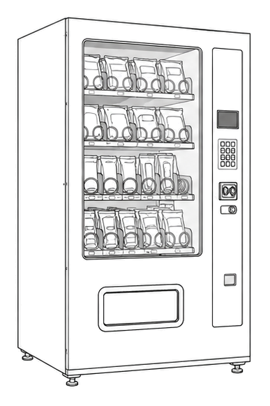
cabinet glass front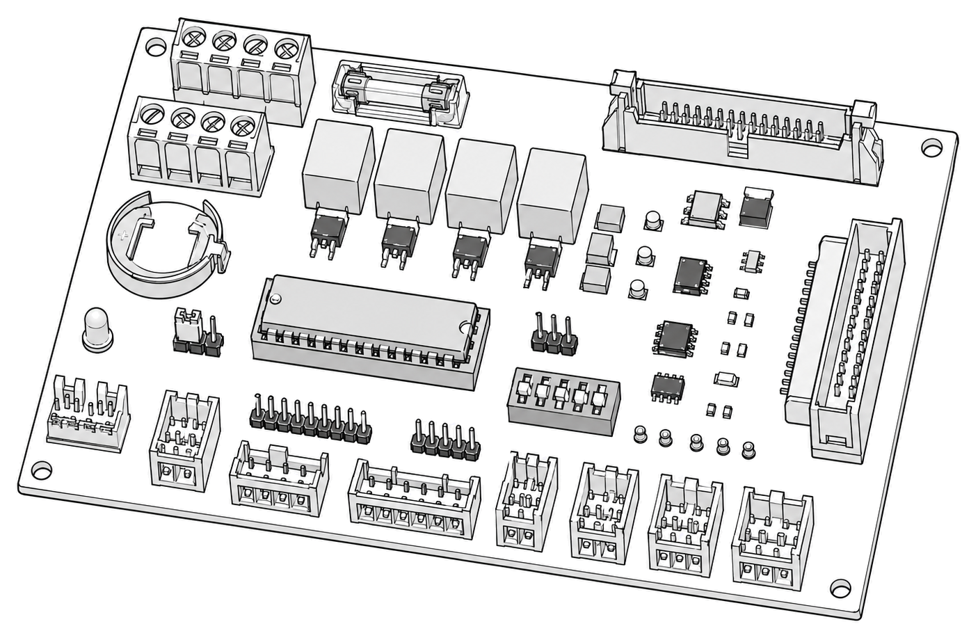 control board generic
 power supply
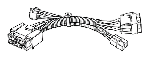 terminal block
Parts status
Exact public parts list not verified yet. Use this route to identify the system before ordering.
Candidate areas for part verification
Other Possible Issues
Switch routes if this symptom is not the closest match.