No Power Diagnostic Flow
Systematic isolation of power input and supply faults from wall outlet to low-voltage output.
Qualified technician handoff: stop before live electrical testing, sealed-system refrigeration work, compressor service, or protected-compartment access unless a qualified technician is handling the work.
- Fuse blows repeatedly after replacement: Immediately discontinue. Indicates dangerous overcurrent. Escalate to advanced technician.
- Burning smell detected at any point: Unplug machine immediately. Do not restart until inspected by qualified technician.
- Visible arcing or sparking: Unplug machine immediately. Fire risk. Contact emergency services if needed.
Checklist
Guided Diagnostic Steps
Work from low-risk checks toward technician-level inspection only when evidence supports it.
You can read or print the route now. The first checkbox click opens the service contact gate.
- 1
Confirm Wall Outlet Power
operator-intermediatelowPlug a known-good device such as a lamp into the wall outlet serving the machine and verify it operates. If the outlet is switched verify the switch is on.
Expected: Known-good device operates confirming outlet has power.
Evidence to note: photo
- 2
Inspect Power Cord
operator-intermediatelowUnplug the machine from the wall. Carefully inspect the entire length of the power cord for damage including cuts pinches melt spots or exposed wires. Also inspect the plug end for bent or scorched prongs.
Flashlight or Work LightStop conditions- Cord is damaged
Expected: Power cord is intact with no visible damage.
Evidence to note: photo
- 3
Check Internal Fuse or Breaker
operator-intermediatehighWith the machine unplugged locate the main fuse or circuit breaker on the power input or power supply assembly. Inspect for a blown fuse or tripped breaker. If a fuse is blown do not replace it until the cause is investigated. If a breaker is tripped reset it once and observe.
Digital MultimeterStop conditions- Fuse blows again immediately after replacement
- Breaker trips again immediately
Expected: Fuse is intact or breaker is in the on position.
Evidence to note: photo
- 4
Verify Low-Voltage Power Supply Output
technician-advancedlive-voltageWith appropriate safety precautions measure the low-voltage DC output from the power supply to the controller. Compare the reading to the expected output rating. If the expected rating is unknown consult the manufacturer specification.
Qualified technician handoff: stop before live electrical testing, sealed-system refrigeration work, compressor service, or protected-compartment access unless a qualified technician is handling the work.
Digital MultimeterStop conditions- Any sign of overheating on the power supply board
- Burning smell
Expected: DC voltage within expected range at power supply output.
Evidence to note: meter-reading
- 5
Check Controller Power Input
technician-advancedlive-voltageVerify that the low-voltage power is reaching the controller board main power input connector. Wiggle the connector gently to check for intermittent connection.
Qualified technician handoff: stop before live electrical testing, sealed-system refrigeration work, compressor service, or protected-compartment access unless a qualified technician is handling the work.
Digital MultimeterExpected: Voltage present at controller input matching power supply output.
Evidence to note: meter-reading
- 6
Resolve Wall Outlet Issue
operator-intermediatelowThe wall outlet does not have confirmed power. Contact building maintenance or a licensed electrician to restore outlet power before proceeding.
Expected: Outlet provides confirmed power.
Evidence to note: note
- 7
Stop: Damaged Power Cord
operator-intermediatelowA damaged power cord is a safety hazard. Do not operate the machine. Unplug the machine and do not reconnect until the power cord is replaced with a correct type and rating.
Expected: Machine disconnected and cord replacement scheduled.
Evidence to note: photo
- 8
Stop: Blown Fuse Investigation Required
operator-intermediatehighThe main fuse is blown. This indicates an overcurrent event. Do not simply replace the fuse without investigating the root cause. Inspect wiring harnesses for shorts and check for failed components. If the cause is unclear escalate to a qualified technician.
Digital MultimeterExpected: Root cause identified and corrected before fuse replacement.
Evidence to note: note
- 9
Resolve: Power Supply Failure Likely
technician-advancedlive-voltageLow-voltage output is absent or out of specification with confirmed line voltage input. The power supply likely requires replacement. Verify the correct replacement part number through the manufacturer or an authorized distributor.
Qualified technician handoff: stop before live electrical testing, sealed-system refrigeration work, compressor service, or protected-compartment access unless a qualified technician is handling the work.
Digital MultimeterExpected: Power supply replaced with correct unit and low-voltage output confirmed.
Evidence to note: meter-reading
- 10
Resolve: Harness Connection Issue
operator-intermediatehighPower reaches the power supply but not the controller. Inspect the harness and connectors between the power supply output and the controller input for damage corrosion or loose pins. Repair or replace the affected harness section.
Digital MultimeterExpected: Continuous confirmed voltage from power supply to controller.
Evidence to note: meter-reading
- 11
Resolve: Controller May Be Faulty
technician-advancedlive-voltagePower supply output is confirmed good and voltage reaches the controller input but the machine still does not function. The controller board may be faulty. Before replacing verify all other connectors on the controller are properly seated and there are no signs of physical damage or burned components on the board.
Qualified technician handoff: stop before live electrical testing, sealed-system refrigeration work, compressor service, or protected-compartment access unless a qualified technician is handling the work.
Digital MultimeterFlashlight or Work LightExpected: Controller replaced or other root cause identified.
Evidence to note: meter-reading
- 12
Stop: Escalate to Licensed Electrician
operator-intermediatelowThe building electrical supply or outlet requires professional attention. Do not attempt wiring repairs without proper licensing. Contact a licensed electrician.
Expected: Building electrical issue resolved by licensed professional.
Evidence to note: note
Tools for this route
Location Help
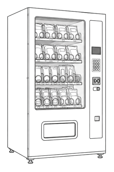
Where to find this
Use this as orientation before touching the machine. It is location help, not a repair instruction.

Start at the front door payment column; match the display, keypad, coin, bill, or card device to the symptom before opening deeper panels.
- Converts line voltage to regulated low-voltage DC for controller, display, and logic circuits.
- Transformer or switching power supply
- Rectifier and filter capacitors
- Voltage regulators
Do not open energized or protected electrical areas unless a qualified technician or licensed electrician is handling the work.
cabinet generic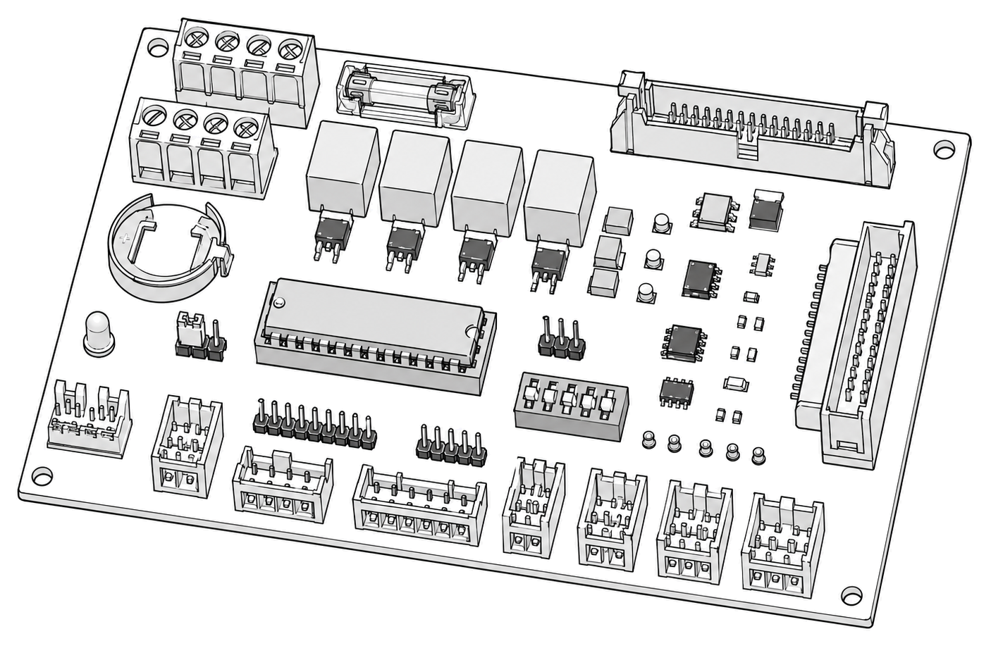 control board generic
 payment column
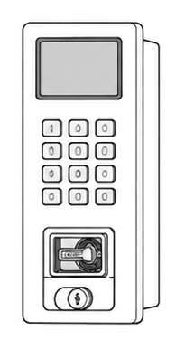 display keypad
Parts status
Exact public parts list not verified yet. Use this route to identify the system before ordering.
Candidate areas for part verification
Other Possible Issues
Switch routes if this symptom is not the closest match.