Display and keypad diagnostic
VendnetUSA 3116
Display and keypad diagnostic
This procedure focuses on verifying the integrity of the display unit, its connecting harnesses, and the controller's ability to properly communicate display information.
- Display connector shows burn marks or melted plastic: stop_and_escalate
- If the display connector shows burn marks or melted plastic, stop and contact a qualified technician.
- If the display does not show any startup content, contact a qualified technician for further electronic review.
Checklist
Guided Diagnostic Steps
Work from low-risk checks toward technician-level inspection only when evidence supports it.
You can read or print the route now. The first checkbox click opens the service contact gate.
- 1
With power off, disconnect and firmly reconnect the display harness a...
operator-intermediatelowWith power off, disconnect and firmly reconnect the display harness at both the controller and the display module.
Flashlight or work lightStop conditions- If the display connector shows burn marks or melted plastic, stop and contact a qualified technician.
- If the display does not show any startup content, contact a qualified technician for further electronic review.
Expected: Initial condition is documented before deeper diagnosis.
Evidence to note: note
- 2
Power on and observe the display during startup.
operator-intermediatelowPower on and observe the display during startup.
Flashlight or work lightStop conditions- If the display connector shows burn marks or melted plastic, stop and contact a qualified technician.
- If the display does not show any startup content, contact a qualified technician for further electronic review.
Expected: Initial condition is documented before deeper diagnosis.
Evidence to note: note
- 3
With power off, disconnect and firmly reconnect the display harness a...
operator-intermediatelowWith power off, disconnect and firmly reconnect the display harness at both the controller and the display module.
Flashlight or work lightStop conditions- If the display connector shows burn marks or melted plastic, stop and contact a qualified technician.
- If the display does not show any startup content, contact a qualified technician for further electronic review.
Expected: Result is documented before continuing the route.
Evidence to note: note
- 4
Power on and observe the display during startup.
operator-intermediatelowPower on and observe the display during startup.
Flashlight or work lightStop conditions- If the display connector shows burn marks or melted plastic, stop and contact a qualified technician.
- If the display does not show any startup content, contact a qualified technician for further electronic review.
Expected: Result is documented before continuing the route.
Evidence to note: note
- 5
Test keypad responsiveness
operator-intermediatelowTest keypad responsiveness
Flashlight or work lightStop conditions- If the display connector shows burn marks or melted plastic, stop and contact a qualified technician.
- If the display does not show any startup content, contact a qualified technician for further electronic review.
Expected: Result is documented before continuing the route.
Evidence to note: note
- 6
Clear any mechanical obstruction
operator-intermediatelowClear any mechanical obstruction
Flashlight or work lightStop conditions- If the display connector shows burn marks or melted plastic, stop and contact a qualified technician.
- If the display does not show any startup content, contact a qualified technician for further electronic review.
Expected: Result is documented before continuing the route.
Evidence to note: note
Tools for this route
Location Help
Where to find this
Use this as orientation before touching the machine. It is location help, not a repair instruction.

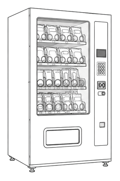
Start at the front door payment column; match the display, keypad, coin, bill, or card device to the symptom before opening deeper panels.
- Central logic board that coordinates vend operations, payment validation, display output, and mode configuration.
- Main control board
- Memory or firmware chip
- Connection headers for harnesses
cabinet generic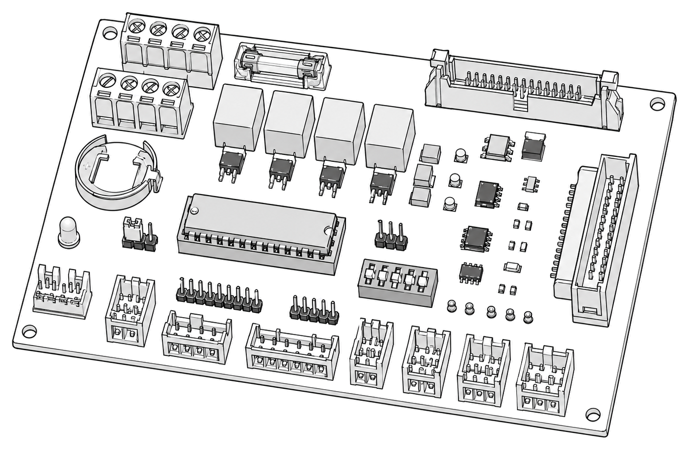 control board generic
 payment column
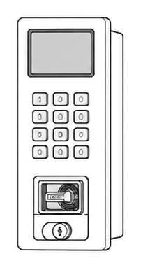 display keypad
Parts status
Exact public parts list not verified yet. Use this route to identify the system before ordering.
Candidate areas for part verification
Other Possible Issues
Switch routes if this symptom is not the closest match.