Controller Board Diagnostic
VendnetUSA 3142 / 3143 / 3085 / MDB 3084
Controller Board Diagnostic
Determines whether the controller board is receiving proper low-voltage supply and producing expected outputs before considering board replacement.
Qualified technician handoff: stop before live electrical testing, sealed-system refrigeration work, compressor service, or protected-compartment access unless a qualified technician is handling the work.
- Controller board shows burn damage: Investigate power supply and harness for overcurrent cause before installing replacement board.
Checklist
Guided Diagnostic Steps
Work from low-risk checks toward technician-level inspection only when evidence supports it.
You can read or print the route now. The first checkbox click opens the service contact gate.
- 1
Visual inspection of controller board
operator-intermediatehighWith machine unplugged, access the controller board. Use a flashlight to inspect for visible damage: bulging capacitors, discoloration, burn spots, cracked traces, corrosion, or loose connectors.
Flashlight or Work LightStop conditions- Visible burning or scorched area on board — do not re-energize until assessed
Expected: Board appears clean with no visible damage. All connectors seated.
Evidence to note: photo
- 2
Check controller low-voltage supply
technician-advancedlive-voltageWith machine plugged in and appropriate PPE, carefully measure the low-voltage supply input to the controller board. Compare reading to manufacturer specification.
Qualified technician handoff: stop before live electrical testing, sealed-system refrigeration work, compressor service, or protected-compartment access unless a qualified technician is handling the work.
Digital MultimeterInsulated GlovesStop conditions- Any sign of overheating near measurement point
- Measurement point wet or corroded beyond safe probing
Expected: Low-voltage supply present and within specification.
Evidence to note: meter-reading
- 3
Verify controller mode and display output
operator-intermediatehighAttempt to enter controller diagnostic or programming mode per machine operating procedure. Observe whether display responds and keypad inputs register.
Expected: Controller enters diagnostic mode, display shows expected menu, keys respond.
Evidence to note: note
Tools for this route
Location Help
Where to find this
Use this as orientation before touching the machine. It is location help, not a repair instruction.

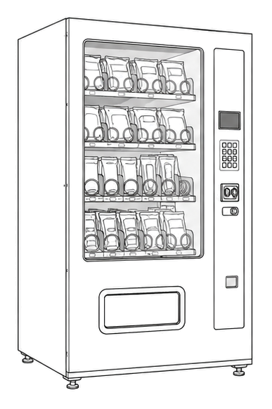
Start at the front door payment column; match the display, keypad, coin, bill, or card device to the symptom before opening deeper panels.
- Central logic board coordinating vend cycles, payment communication, temperature control, and display output.
- Main controller PCB
- Onboard fuses or protection devices
- Firmware IC
Do not open energized or protected electrical areas unless a qualified technician or licensed electrician is handling the work.
cabinet drink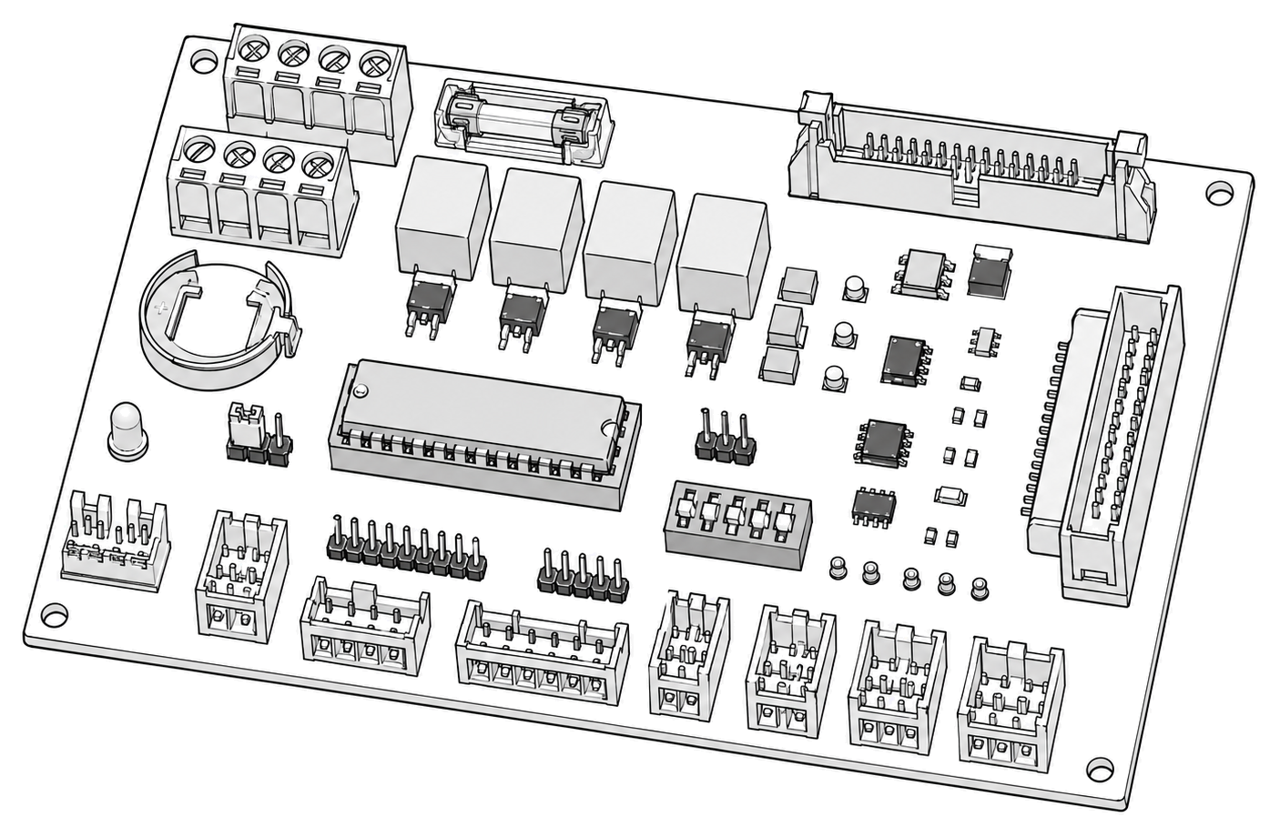 control board generic
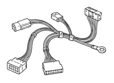 wiring harness
 payment column
Parts status
Exact public parts list not verified yet. Use this route to identify the system before ordering.
Candidate areas for part verification
Other Possible Issues
Switch routes if this symptom is not the closest match.