Reader Has No Power with MDB Connected
VendnetUSA Greenlite Cashle
Reader Has No Power with MDB Connected
Systematic check of power pathway from machine controller through MDB harness to the reader when the physical connection appears intact
Qualified technician handoff: stop before live electrical testing, sealed-system refrigeration work, compressor service, or protected-compartment access unless a qualified technician is handling the work.
- Visible damage to wiring or connectors: Stop and hand off to qualified technician
Checklist
Guided Diagnostic Steps
Work from low-risk checks toward technician-level inspection only when evidence supports it.
You can read or print the route now. The first checkbox click opens the service contact gate.
- 1
Verify Vending Machine is Powered On
operator-intermediatelowConfirm the host vending machine is fully powered on and the control display is active. Do not access any internal components yet.
Expected: Machine display or indicators show the machine controller is operational
Evidence to note: photo
- 2
Inspect MDB Connection at Reader
operator-intermediatehighWith a flashlight, visually examine where the MDB cable connects to the reader. Look for full seating of the connector, any bent pins visible from outside, and signs of corrosion or debris. Do not disconnect yet.
Flashlight or Work LightStop conditions- Connector is hot to touch
- Signs of melting or burning
Expected: MDB connector appears fully seated and free of visible damage
Evidence to note: meter-reading
- 3
Inspect MDB Connection at Machine Controller
operator-intermediatehighAccess the machine controller area per the machine's service procedures. Visually examine where the MDB cable connects to the controller's cashless port. Check for full seating and condition.
Flashlight or Work LightExpected: MDB connector at controller is fully seated and in good condition
Evidence to note: meter-reading
- 4
Check MDB Voltage at Controller Output
technician-advancedlive-voltageMeasure voltage at the machine controller's MDB cashless output port. This isolates whether the issue is the cable or the controller output. Consult manufacturer specifications for expected values.
Qualified technician handoff: stop before live electrical testing, sealed-system refrigeration work, compressor service, or protected-compartment access unless a qualified technician is handling the work.
Digital MultimeterStop conditions- Any sign of sparking
- Unexpected voltage levels
Expected: Voltage present at controller MDB output within specification
Evidence to note: meter-reading
- 5
Inspect MDB Connector Pins for Damage
operator-intermediatehighCarefully examine the pins inside both the reader-side and controller-side MDB connectors. Look for bent pins, corrosion, pushed-back pins, or foreign material. Use a flashlight for better visibility.
Flashlight or Work LightExpected: All pins are straight, clean, and properly positioned
Evidence to note: photo
- 6
Reconnect MDB Cable to Reader
operator-intermediatehighAlign the MDB connector carefully with the reader port, ensuring correct orientation. Seat the connector firmly but without excessive force. It should click or seat fully with moderate pressure.
Stop conditions- Connector does not fit without excessive force
- Any resistance that feels abnormal
Expected: Connector seats fully and reader shows LED activity
Evidence to note: photo
- 7
Assess Cellular Signal Environment
operator-intermediatelowUsing a personal cellphone at the reader location, check the cellular signal strength. Note the carrier if possible and whether it matches the reader's wireless carrier. Walk around the machine area to see if signal varies.
Cellphone for Signal TestingExpected: Cellphone shows at least moderate signal strength at reader location
Evidence to note: meter-reading
- 8
Document LED Error Pattern
operator-intermediatelowCarefully observe and record the LED color and any blinking pattern. Note the approximate blink rate (fast, slow, irregular). Record how long the pattern persists and whether it changes over time.
Notepad or Documentation ToolExpected: Detailed written record of LED color, pattern, and duration
Evidence to note: photo
- 9
Power Cycle the Reader
operator-intermediatehighDisconnect the reader from power by unplugging the MDB cable from the reader. Wait 30 seconds. Reconnect the MDB cable and observe the LED behavior during startup.
Stop conditions- Reader becomes hot during startup
- Unusual sounds occur
Expected: Reader goes through a startup sequence and either returns to normal operation or repeats the error pattern
Evidence to note: note
- 10
Inspect All Physical Connections Thoroughly
operator-intermediatehighCheck every connection point in the reader system: MDB at reader, MDB at controller, any ground connections, and any auxiliary connections. Gently wiggle connectors while observing reader LED to check for intermittent contact.
Flashlight or Work LightStop conditions- Any connector sparks or shows arcing during wiggle test
Expected: All connections are secure with no change in reader behavior during wiggle test
Evidence to note: note
Tools for this route
Location Help
Where to find this
Use this as orientation before touching the machine. It is location help, not a repair instruction.

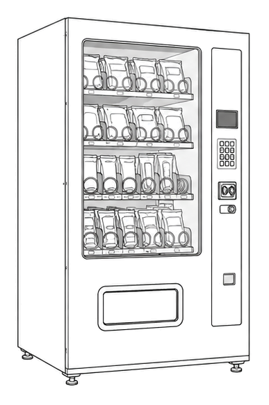
Start at the affected product shelf or selection row; compare the tray, coil, and product path with a nearby working selection.
- Physical wiring pathways between reader and vending machine controller, and any external antennas
- MDB cable
- Cable strain reliefs
- Connector housings
Do not open energized or protected electrical areas unless a qualified technician or licensed electrician is handling the work.
cabinet generic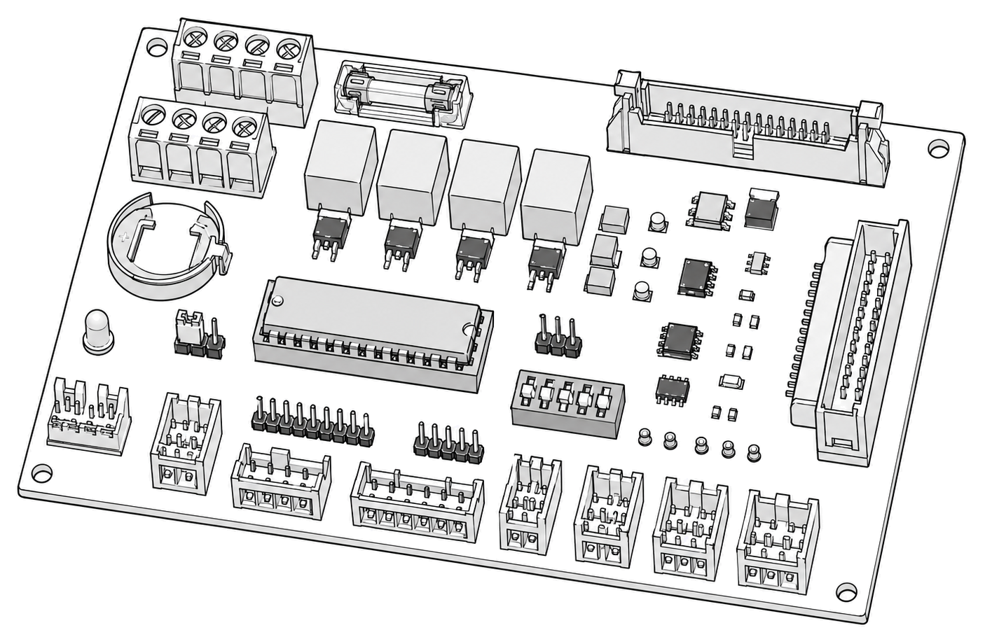 control board generic
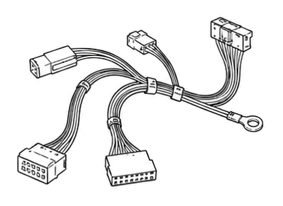 wiring harness
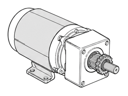 vend motor
Parts status
Exact public parts list not verified yet. Use this route to identify the system before ordering.
Candidate areas for part verification
Other Possible Issues
Switch routes if this symptom is not the closest match.