Machine Completely Unresponsive - Power Input Diagnostic
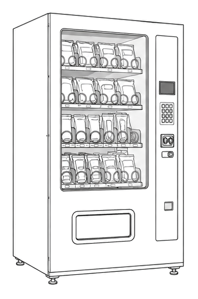
Royal Vendors RVV NG Vender
Machine Completely Unresponsive - Power Input Diagnostic
Step-by-step diagnosis when the machine shows no signs of life, starting from the wall outlet and working inward.
Qualified technician handoff: stop before live electrical testing, sealed-system refrigeration work, compressor service, or protected-compartment access unless a qualified technician is handling the work.
- Evidence of electrical fire, arcing, or component failure with heat damage: De-energize immediately. Tag machine as unsafe for operation.
Checklist
Guided Diagnostic Steps
Work from low-risk checks toward technician-level inspection only when evidence supports it.
You can read or print the route now. The first checkbox click opens the service contact gate.
- 1
Verify Wall Outlet Power
technician-advancedlive-voltageUse a known-good lamp or outlet tester at the wall outlet to confirm facility power is present. If using a multimeter, measure across the hot and neutral terminals.
Qualified technician handoff: stop before live electrical testing, sealed-system refrigeration work, compressor service, or protected-compartment access unless a qualified technician is handling the work.
Digital MultimeterOutlet TesterStop conditions- Outlet shows signs of arcing or damage - do not insert tester
Expected: Facility power confirmed present at the outlet.
Evidence to note: meter-reading
- 2
Inspect Power Cord and Plug
operator-intermediatelowUnplug the machine. Visually and physically inspect the entire power cord length, plug body, and strain relief at the machine entry. Look for cuts, burns, melted areas, or loose prongs.
Flashlight or Work LightStop conditions- Cord is hot to touch while plugged in
- Burn marks on plug or cord
Expected: Power cord and plug are undamaged and in good condition.
Evidence to note: photo
- 3
Check Internal Fuse and Terminal Block
operator-intermediatehighWith machine unplugged and capacitors allowed to discharge, open the main access panel. Locate the main fuse holder and terminal block. Inspect for blown fuse, loose connections, or signs of overheating. Test fuse continuity with multimeter.
Qualified technician handoff: stop before live electrical testing, sealed-system refrigeration work, compressor service, or protected-compartment access unless a qualified technician is handling the work.
Digital MultimeterFlashlight or Work LightStop conditions- Evidence of electrical arcing or burning near terminal block
- Fuse holder cracked or heat-damaged
Expected: Main fuse has continuity. Terminal block connections are tight and show no heat damage.
Evidence to note: meter-reading
- 4
Verify Low-Voltage Power Supply Output
technician-advancedlive-voltageWith machine safely powered at the outlet and main fuse confirmed good, carefully measure the low-voltage DC output at the power supply. Use caution as primary-side AC is still energized nearby.
Qualified technician handoff: stop before live electrical testing, sealed-system refrigeration work, compressor service, or protected-compartment access unless a qualified technician is handling the work.
Digital MultimeterStop conditions- Any sign of component bulging, leaking, or burning on power supply board
- Unusual smell from power supply area
Expected: Low-voltage DC output is present at the power supply output terminals within expected range.
Evidence to note: meter-reading
- 5
Power Input Diagnostic Summary
operator-intermediatelowReview all findings from previous steps. Document what was confirmed good and what remains uncertain.
Expected: Clear diagnostic summary established with identified fault or next area to investigate.
Evidence to note: note
Tools for this route
Location Help
Where to find this
Use this as orientation before touching the machine. It is location help, not a repair instruction.
Start outside the machine at the outlet and cord, then identify the power entry area before any protected-compartment inspection.
- Provides main AC power connection and primary overcurrent protection for the machine.
- Power cord
- Terminal block or input connector
- Main fuse or circuit breaker
Do not open energized or protected electrical areas unless a qualified technician or licensed electrician is handling the work.
cabinet glass front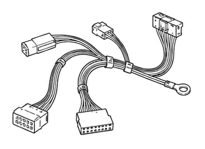 wiring harness
 power supply
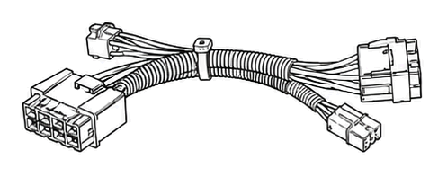 terminal block
Parts status
Exact public parts list not verified yet. Use this route to identify the system before ordering.
Candidate areas for part verification
Other Possible Issues
Switch routes if this symptom is not the closest match.