Vend Motor No-Run Diagnostic
Royal Vendors RVV NG Vender
Vend Motor No-Run Diagnostic
Diagnoses why a vend motor fails to operate when a selection is made, distinguishing between motor, harness, controller, and mechanical causes.
Qualified technician handoff: stop before live electrical testing, sealed-system refrigeration work, compressor service, or protected-compartment access unless a qualified technician is handling the work.
- Multiple motor harness connectors show heat damage or multiple motors have failed: Suspect overcurrent or design issue. Do not continue replacing motors until root cause is found.
Checklist
Guided Diagnostic Steps
Work from low-risk checks toward technician-level inspection only when evidence supports it.
You can read or print the route now. The first checkbox click opens the service contact gate.
- 1
Confirm Single vs. Multi-Column Failure
operator-intermediatelowAttempt test vends from at least three different columns. Record which columns work and which do not.
Stop conditions- Machine does not accept any selection
Expected: Pattern established: single column failure or multi-column failure.
Evidence to note: note
- 2
Inspect for Product Jam or Mechanical Binding
operator-intermediatelowWith machine powered off or in test mode per manufacturer procedure, manually check the affected column for product jam, misalignment, or mechanical resistance in the drive mechanism.
Flashlight or Work LightExpected: Drive mechanism moves freely with no obstruction.
Evidence to note: note
- 3
Check Motor Harness Connection
operator-intermediatelowWith power off, locate the motor harness connector for the affected column. Disconnect and inspect connector pins for corrosion, bent pins, or pushed-back contacts. Reconnect firmly.
Flashlight or Work LightStop conditions- Heat-damaged connector detected
Expected: Connector is clean, pins are straight, and connector seats fully with positive engagement.
Evidence to note: photo
- 4
Test Motor and Controller Signal
technician-advancedhighWith appropriate safety precautions, test whether the controller outputs drive signal to the motor connector when the column is selected. Then test motor winding resistance.
Digital MultimeterExpected: Controller outputs appropriate drive signal when column selected. Motor winding shows expected resistance.
Evidence to note: meter-reading
Tools for this route
Location Help
Where to find this
Use this as orientation before touching the machine. It is location help, not a repair instruction.
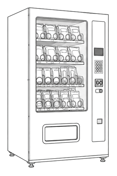
Start at the front door payment column; match the display, keypad, coin, bill, or card device to the symptom before opening deeper panels.
- Executes vend logic, monitors sensors, controls motors, manages refrigeration, and coordinates payment communication.
- Main controller board
- Microprocessor
- Memory chip for vend settings
Do not open sealed-system or compressor areas unless a qualified refrigeration technician is handling the work.
cabinet glass front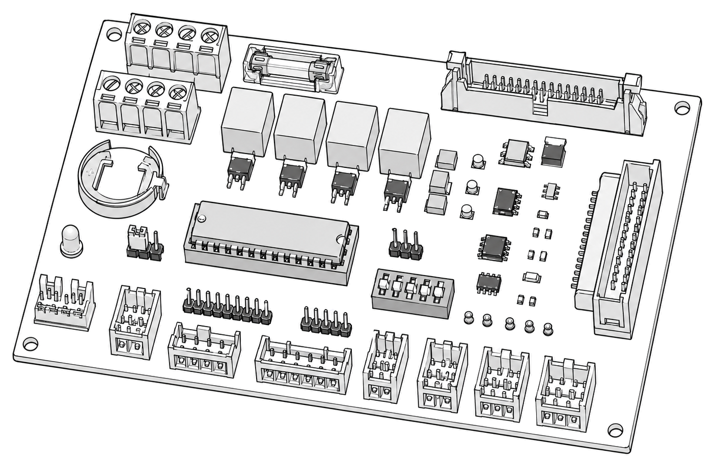 control board generic
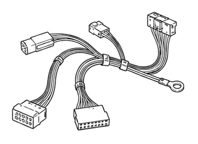 wiring harness
 payment column
Parts status
Exact public parts list not verified yet. Use this route to identify the system before ordering.
Candidate areas for part verification
Other Possible Issues
Switch routes if this symptom is not the closest match.