Diagnose Completely Dead Machine
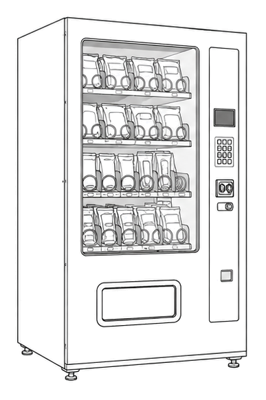
VendnetUSA Model 3003 MDB
Diagnose Completely Dead Machine
Step-by-step flow to determine why the Model 3003 MDB shows no signs of power — no display, no lights, no motor response.
Qualified technician handoff: stop before live electrical testing, sealed-system refrigeration work, compressor service, or protected-compartment access unless a qualified technician is handling the work.
- Live-voltage measurement required: Stop. Hand off to qualified technician with appropriate PPE and training.
- Repeatedly blown fuse: Do not replace again. Indicates short circuit. Hand off for root-cause investigation.
- Burnt smell or visible burning: Unplug immediately. Do not reapply power. Hand off to qualified technician.
Checklist
Guided Diagnostic Steps
Work from low-risk checks toward technician-level inspection only when evidence supports it.
You can read or print the route now. The first checkbox click opens the service contact gate.
- 1
Verify Wall Outlet Power
operator-intermediatelowUse a known-good lamp or outlet tester to confirm the wall outlet provides power. Do not plug the machine into a suspect outlet.
Outlet TesterStop conditions- Outlet shows wiring fault on tester — do not use outlet
Expected: Outlet tester indicates correct wiring and voltage present.
Evidence to note: meter-reading
- 2
Inspect Power Cord and Plug
operator-intermediatelowUnplug the machine. Visually inspect the full length of the power cord for cuts, kinks, melted areas, or damaged prongs on the plug.
Flashlight or Work LightStop conditions- Cord has exposed conductors — do not plug in
- Plug prongs are bent, burnt, or loose — do not plug in
Expected: Power cord is intact with no visible damage.
Evidence to note: photo
- 3
Check Main Fuse or Circuit Breaker
operator-intermediatehighWith machine unplugged, locate the main fuse holder or circuit breaker. Remove fuse and test for continuity, or verify breaker is in the ON position.
Digital MultimeterFlashlight or Work LightStop conditions- Fuse holder area shows heat discoloration or melting — do not replace fuse, investigate cause first
Expected: Fuse shows continuity or breaker is in ON position.
Evidence to note: meter-reading
- 4
Investigate Blown Fuse Before Replacing
operator-intermediatehighA blown fuse indicates overcurrent. Before replacing, visually inspect for short circuits: check for pinched wires, burnt components, or water intrusion. Do not install a higher-amperage fuse.
Flashlight or Work LightStop conditions- Burnt wiring or component found — do not apply power
- Water present near fuse or wiring — do not apply power
Expected: No visible short circuit cause found; safe to install correct replacement fuse.
Evidence to note: photo
- 5
Verify Low-Voltage Supply to Controller
technician-advancedlive-voltageWith machine plugged in and fuse confirmed good, carefully check for low-voltage output from the power supply area to the controller board. This step requires live-voltage measurement at the power supply output.
Qualified technician handoff: stop before live electrical testing, sealed-system refrigeration work, compressor service, or protected-compartment access unless a qualified technician is handling the work.
Digital MultimeterStop conditions- Any sign of arcing, sparking, or unusual smell during measurement — unplug immediately
Expected: Low-voltage DC present at controller power input pins.
Evidence to note: meter-reading
- 6
Assess Controller Board Condition
operator-intermediatehighWith machine unplugged, visually inspect the controller board for burnt components, bulging capacitors, liquid damage, or cracked traces.
Flashlight or Work LightStop conditions- Board shows burnt area — do not apply power
- Liquid visible on board — do not apply power
Expected: Controller board shows no visible damage.
Evidence to note: photo
Tools for this route
Parts status
Exact public parts list not verified yet. Use this route to identify the system before ordering.
Candidate areas for part verification
Other Possible Issues
Switch routes if this symptom is not the closest match.