Vend Motor Not Activating
VendnetUSA VendnetUSA Vending
Vend Motor Not Activating
Determines whether a vend motor failure is due to the motor itself, its harness, the controller command signal, or a mechanical jam in the product path.
Qualified technician handoff: stop before live electrical testing, sealed-system refrigeration work, compressor service, or protected-compartment access unless a qualified technician is handling the work.
- Multiple motors failing simultaneously: Escalate — likely controller or power supply issue, not individual motors.
- Burning smell from motor area: Immediately disconnect power. Do not attempt further motor testing. Tag machine out of service.
Checklist
Guided Diagnostic Steps
Work from low-risk checks toward technician-level inspection only when evidence supports it.
You can read or print the route now. The first checkbox click opens the service contact gate.
- 1
Visual Inspection of Vend Motor Area
technician-advancedtechnicianWith machine power off, shine a flashlight into the vend tray area of the affected selection. Look for any product, packaging, or debris that could physically prevent the coil or pusher from turning. Check that the tray is fully seated in its rails.
Flashlight or Work LightStop conditions- visible damage to tray mechanism — do not force, hand off
Expected: Clear view of the coil/pusher area confirming no obstruction and proper tray seating.
Evidence to note: photo
- 2
Clear Product Jam
technician-advancedtechnicianWith power off, carefully remove the obstructing product or debris from the coil path. Do not use sharp tools that could damage the coil or tray. Re-seat the tray if it was displaced.
Stop conditions- mechanism will not move even with obstruction removed — mechanical damage suspected
Expected: Coil or pusher can be gently rotated by hand through its full range without resistance.
Evidence to note: note
- 3
Check Motor Harness Voltage
technician-advancedlive-voltageWith power on and machine in a safe test state, initiate a test vend for the affected selection. Measure voltage at the motor harness connector while the controller attempts to drive the motor. Use appropriate meter probes and keep fingers clear of moving parts.
Qualified technician handoff: stop before live electrical testing, sealed-system refrigeration work, compressor service, or protected-compartment access unless a qualified technician is handling the work.
Digital MultimeterStop conditions- any sign of burning or overheating at connector — disconnect power immediately
Evidence to note: meter-reading
- 4
Check Motor Harness Continuity
technician-advancedtechnicianWith power disconnected, disconnect the motor harness at both the motor end and the controller end. Measure continuity of each wire in the harness. Also inspect connector pins for corrosion, bent pins, or loose crimps.
Digital MultimeterExpected: All harness wires show continuity (low resistance). Connectors are clean and pins are straight and secure.
Evidence to note: meter-reading
- 5
Verify Wall Outlet Power
technician-advancedlive-voltageUse an outlet tester or multimeter to confirm the wall outlet is providing correct voltage. Check that the outlet is not on a tripped GFCI or switched circuit.
Qualified technician handoff: stop before live electrical testing, sealed-system refrigeration work, compressor service, or protected-compartment access unless a qualified technician is handling the work.
Digital MultimeterOutlet TesterStop conditions- hot-to-ground voltage detected on outlet — do not plug machine in, contact facility electrician
Expected: Outlet tester shows correct wiring. Voltage reading matches facility spec. requiresFieldValidation for local voltage.
Evidence to note: meter-reading
- 6
Inspect Power Cord
owner-basicbasicVisually inspect the full length of the power cord from plug to machine entry point. Look for cuts, kinks, burn marks, or signs of damage. Feel along the cord (unplugged) for soft spots indicating internal damage.
Flashlight or Work LightStop conditions- cord is hot to the touch while connected — disconnect immediately
Expected: Power cord is intact, pliable, and free of damage.
Evidence to note: photo
- 7
Check Main Fuse
technician-advancedtechnicianWith machine unplugged, locate the main fuse. Remove and measure continuity through the fuse. A blown fuse shows open circuit. Inspect fuse holder for signs of overheating or corrosion.
Digital MultimeterStop conditions- fuse holder shows heat damage or melting — do not install new fuse, investigate short circuit
Expected: Fuse shows continuity. Fuse holder is clean and undamaged.
Evidence to note: meter-reading
- 8
Inspect Delivery Path
technician-advancedtechnicianWith power off, open the machine and visually trace the path from the lowest tray to the customer pickup area. Look for fallen products, packaging material, or debris obstructing the delivery path. Check that the lift basket or conveyor is at its home position.
Flashlight or Work LightStop conditions- lift mechanism is physically damaged — do not force movement
Expected: Delivery path is clear. Lift or conveyor is at home position.
Evidence to note: photo
- 9
Inspect Delivery Sensor
technician-advancedtechnicianLocate the delivery sensor (typically optical or mechanical). Clean the sensor face or lens with a soft dry cloth. Check that the sensor is firmly mounted and aligned with its target or emitter.
Flashlight or Work LightExpected: Sensor is clean, firmly mounted, and properly aligned.
Evidence to note: photo
- 10
Perform Test Vend
technician-advancedtechnicianPower on machine. Place a test product in the lowest tray. Initiate a vend from that selection. Observe whether the product successfully reaches the customer pickup area.
Expected: Product dispenses and lands in customer pickup area.
Evidence to note: note
- 11
Visual Inspection of Coin Tubes
technician-advancedtechnicianOpen the coin mechanism area and visually inspect each coin tube. Check tube fill levels and look for coins that are stuck, tilted, or stacked at an angle. Look for foreign objects or debris.
Flashlight or Work LightExpected: All coin tubes show normal coin levels with coins stacked neatly. No foreign objects visible.
Evidence to note: photo
- 12
Test Coin Dispense from Service Mode
technician-advancedtechnicianEnter service mode. Navigate to the coin tube fill or dispense test function. Initiate a test dispense for each denomination. Observe whether coins are ejected correctly.
Stop conditions- coins jam during dispense and cannot be safely cleared — hand off
Expected: Each test dispense ejects the correct number and denomination of coins.
Evidence to note: note
Tools for this route
Location Help
Where to find this
Use this as orientation before touching the machine. It is location help, not a repair instruction.

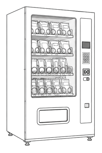
Start at the affected product shelf or selection row; compare the tray, coil, and product path with a nearby working selection.
- Drives product dispensing mechanisms to deliver selected items
- vend motors
- motor harness
- tray mechanisms
Do not open energized or protected electrical areas unless a qualified technician or licensed electrician is handling the work.
cabinet generic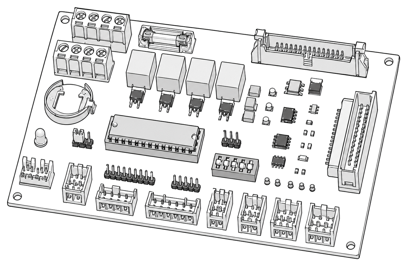 control board generic
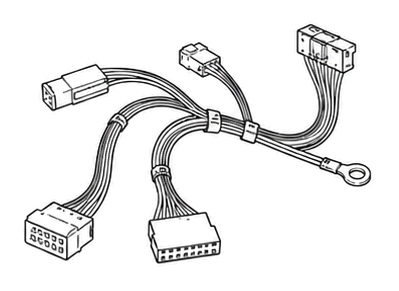 wiring harness
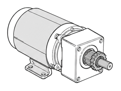 vend motor
Parts status
Exact public parts list not verified yet. Use this route to identify the system before ordering.
Candidate areas for part verification
Other Possible Issues
Switch routes if this symptom is not the closest match.